Serial To Parallel Converter Verilog Code For Full >>> bit.ly/2w1PVbF. Dec 20, 2014 > for 6 to 16 bit programmable parallel to serial converter. Is that a simple loadable shift register? Draw a picture or just add more information. Maybe its stuck. Report post Edit Delete Quote selected text Reply Reply with quote. Re: verilog/vhdl code for programmable parallel to serial converter. Author: anjali k.
WATCH A BETTER QUALITY VIDEO OF THIS HERE: We held a nude in and a body freedom parade as our annual event and also as a protest against the nudity ban that can send you to jail for a year just for taking your clothes off. This one was denied by the SFPD also. Semejnij nudizm torrent. Our lawyers Gill Sperlein and Larry Walters had to go to court to fight for this permit. We actually got a permit for it after having dozens of permits denied. This parade was very special.
1 2 3 4 5 6 7 8 9 10 11 12 13 14 15 16 17 18 19 20 21 module piso1 (sout,sin,clk ); output sout; input [ 3: 0 ]sin; input clk; wire [ 3: 0 ]q; inv u1 (p,sl ); and1 u2 (n,sin [ 1 ],p ); and1 u3 (r,sl,q [ 0 ] ); or1 u4 (s,n,r ); and1 u5 (t,sin [ 2 ],p ); and1 u6 (u,sl,q [ 1 ] ); or1 u7 (v,u,t ); and1 u8 (w,sin [ 3 ],p ); and1 u9 (y,sl,q [ 2 ] ); or1 u10 (z,w,y ); dff1 u11 (q [ 0 ],sin [ 0 ],clk ); dff1 u12 (q [ 1 ],s,clk ); dff1 u13 (q [ 2 ],v,clk ); dff1 u14 (q [ 3 ],z,clk ); assign sout = q [ 3 ]; endmodule. Easy tv usb 20 analog tv receiver driver manual.
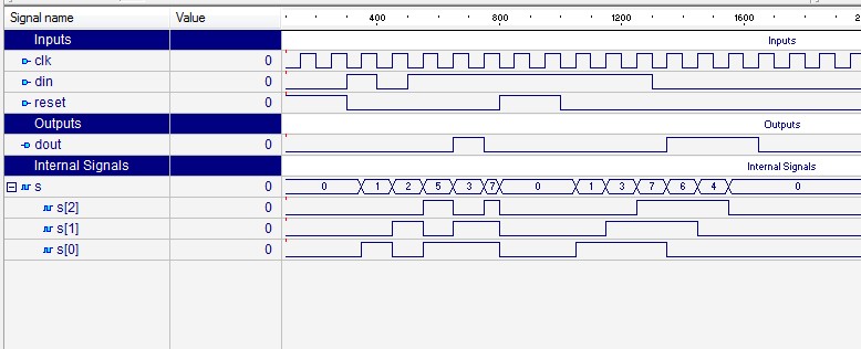
I am making a parallel to serial converter using ring counter in verilog. The ring counter is working fine but the Parallel to serial converter is not working properly and I am getting x undefined result. I am providing the code kindly help me finding the problem. TOP module PtoSTOP; reg clk,rst; wire [3:0] myout; wire out; Ring a(clk,rst,myout); parToser x(myout,clk,rst,out); initial begin clk=1; rst=1; #1 rst=0; end always #2 clk=~clk; endmodule Parallel TO Serial Converter module parToser(myout,clk,rst,out); input clk,rst; input [3:0] myout; output reg out; reg [2:0]i; always @(posedge clk or posedge rst) begin if(rst) begin out. I think the main issue you are seeing is part of parToser.
You have reg [2:0]i; which you increment and use to address input [3:0] myout; but i can hold values 0 to 7, half of which is outside the address range of [3:0] myout. You should be seeing a simulation error about out of range addressing. Also you have included a few flip-flops with a reset condition but not added the reset to the sensitivity list in 'parToser' & 'Ring': always @(posedge clk) Should be: always @(posedge clk or posedge rst) With out this trigger your out, i and myout variables will be x, as they have not been set to a known condition. NB: parToser i = i+1; should be i.